A few weeks ago, my garage remote died. Completely. No LED, no click, no signs of life even after replacing the battery.
Normally, this would be annoying enough, but my house relies heavily on HomeKit. Lights, blinds, cameras, fans - everything responds to Siri… except the garage. And now, even the dumb remote wasn’t working.
But instead of buying a $90 replacement remote or a $250 HomeKit-enabled garage opener, I had a different thought:
What if I use this as an opportunity to learn something… and make my garage smart while I’m at it?
So that’s exactly what I did.
For less than $22 AUD, I turned my dumb garage door opener into a fully HomeKit-compatible accessory using an ESP32, a relay, a DC to DC buck converter, some careful wiring, and my own custom firmware.
The first half of this post will go through the hardware side of things:
- How garage door openers work
- What parts you need
- How to wire everything
- Real photos from my build
- Troubleshooting tips
In the second half I’ll go through the software side of things - but if you don’t want to bother with that I’ll also post the entire source code as a public GitHub repository (with a proper README, build instructions, and maybe even a few example configs) so you can just clone and run it right away.
The Hardware
🧠 Understanding Your Garage Door Opener
Even “dumb” garage door openers are surprisingly simple. They’re almost always controlled by a momentary short between two terminals:
- One labelled something like COM, COMMON, or GND
- The other labelled PUSH BUTTON, SW, “NEG SWITCH”, etc.
Here’s what mine looks like: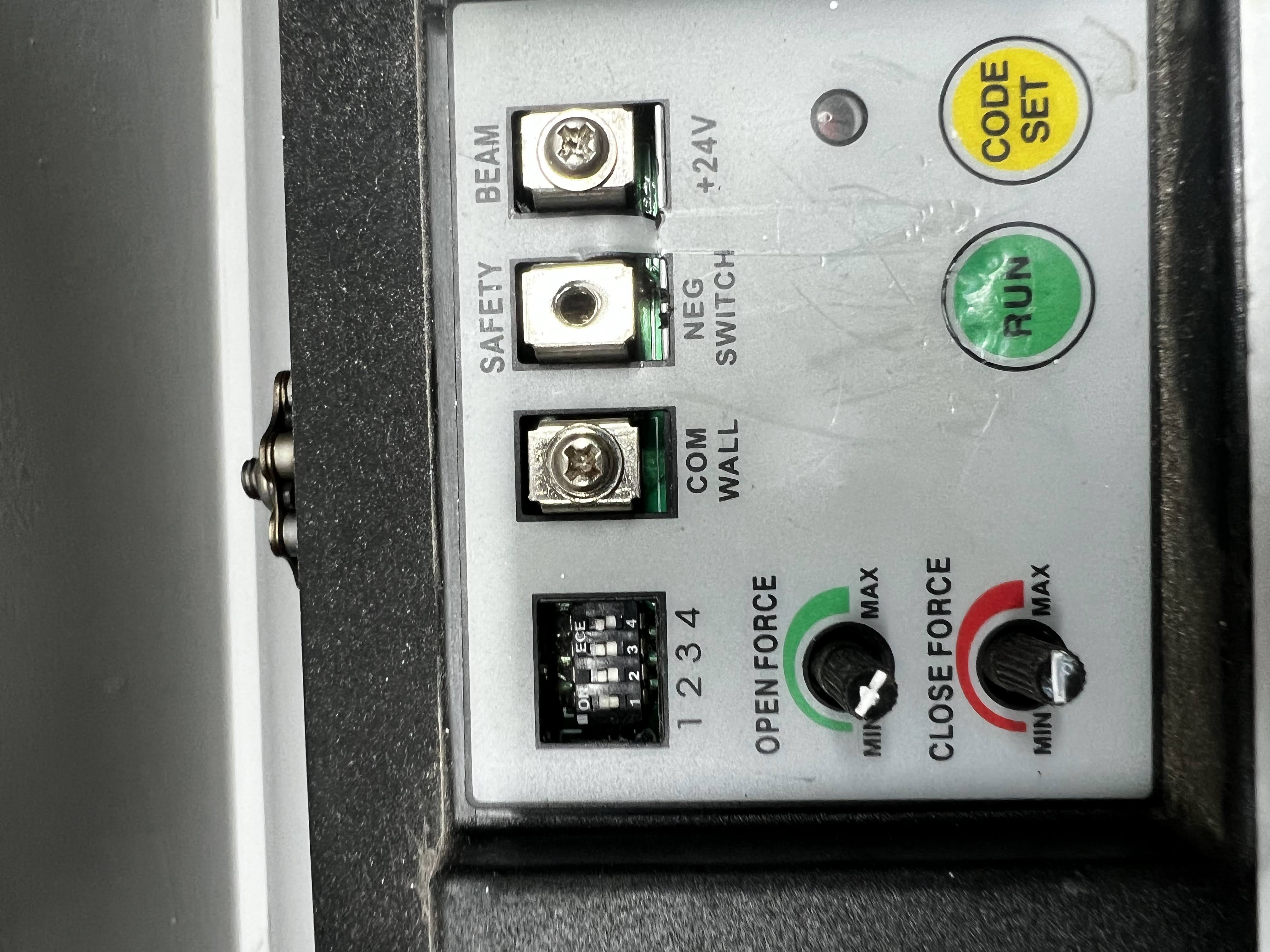
The wall button in your garage is nothing more than a switch that temporarily connects those two terminals. Short them with a screwdriver, and the door will open or close. This simplicity makes garage doors the perfect HomeKit DIY project - you just need a relay that can simulate a button press.
🧩 Parts List (Everything I Used - ~$21 Total)
I bought all the components from Temu. Yes, Temu can be hit-or-miss with quality in general, but I’ve been consistently impressed with their basic electronic parts and microcontrollers - everything I’ve received so far has been perfectly usable, correctly specced, and performed just as well as name-brand equivalents, often at a fraction of the price. Your mileage may vary with other categories, but for this kind of project they’ve been spot-on.
These are the exact parts from my build:
ESP32 Dev Board
- https://share.temu.com/xWgaTqWLm9A
- $4.97
- Serves as the main microcontroller for the smart garage opener, running the code to connect to Wi-Fi, receive remote commands, and trigger the relay.
DC-DC Buck Converter (24V → 5V)
- https://share.temu.com/S7TTOrnP9dA
- $4.66
- Steps down the garage door opener’s 24V power supply to a stable 5V to safely power the ESP32 and relay module without risking damage to sensitive electronics.
1 Channel Relay Module
- https://share.temu.com/PN6dg31uOSA
- $5.78
- Acts as the high-voltage switch to activate the garage door opener’s motor circuit when signaled by the ESP32, allowing low-voltage control of the 24V garage hardware.
Breadboard
- https://share.temu.com/zobt7wqzyaA
- $2.99
- Provides a solderless prototyping platform for assembling and testing the circuit connections between the ESP32, relay, converter, and wiring.
Wiring
- https://share.temu.com/eznypyM2xyA
- $2.35
- Cables for making flexible connections on the breadboard between all components in this prototype setup.
🔌 Step 1 - Mounting and Power
Most garage openers provide +24V and GND for accessories. In my garage, the GND was labelled as COM WALL. Here’s my buck converter + ESP32 setup:
Garage +24V      → Buck Converter VIN+
Garage COMWALL   → Buck Converter VIN−
In case you’re confused, VIN stands for Vault Input and GND stands for Ground.
So what this does is gets the 24 voltage from the garage, and turns it down to 5 volts - which is the voltage level our ESP32 can take in without frying. This keeps everything powered 24/7 without needing a separate wall charger.
So right now we have our DC Buck Converter taking in 24 volts and stepping it down to 5 volts. Let’s now connect our Buck Converter to our ESP32 so we can safely power it.
Buck Converter OUT 5V  → ESP32 VIN
Buck Converter OUT GND → ESP32 GND
🪛 Step 2 - Wiring the ESP32 and Relay
Now that the ESP32 is safely powered from the buck converter, the next step is wiring it to the relay module so it can actually control when the garage door opens or closes.
The ESP32 can only output a tiny 3.3V signal - nowhere near enough to directly trigger the garage opener’s switch terminals. So instead, we give it a helper: a 1-Channel Relay Module.
Think of the relay as a programmable finger.
When the ESP32 tells it to activate, the relay “presses the button” by closing its internal contacts.
A relay module has two sides:
- Input Side - where the ESP32 tells the relay to switch
- Output Side - the screw terminals that will connect to the garage opener (we’ll handle these in Step 3)
For now, we’re wiring only the input side.
Most relay modules have these pins on the input:
- VCC - Usually 5V
- GND - Ground
- IN - The control pin the ESP32 toggles
Here’s how to wire it:
ESP32 5V   → Relay VCC
ESP32 GND  → Relay GND
ESP32 GPIO22 (or any spare digital pin) → Relay IN
It doesn’t have to be GPIO22 - you can use almost any free digital pin. I chose 22 because:
- It’s free on most ESP32 dev boards
- It’s easy to access on a breadboard
- It doesn’t overlap with UART, flash, or special-purpose pins
Once this is connected, the ESP32 can activate the relay by simply driving the IN pin HIGH.
That’s all there is to it - the relay now has power, and the ESP32 officially controls a physical output on your garage hardware.
At this point:
- The ESP32 is powered
- The relay is powered
- The ESP32 can control the relay
But the relay isn’t actually connected to the garage door yet - all we’ve done is set up the control side.
That part comes next.
🛠️ Step 3 - Wiring the Relay to the Garage Door
With the relay now under the ESP32’s control, it’s finally time to connect it to the garage door opener itself. This is the part that makes the whole project actually do something.
Every garage door opener has two terminals dedicated to the wall button. When you press the button on the wall, you’re not sending a voltage - you’re simply shorting those two terminals together momentarily.
On my opener, these terminals were labelled:
- COM WALL
- NEG SWITCH
Your opener may use slightly different names, but the concept is always the same: one is a common ground, one is the trigger.
A relay module has three screw terminals on its output side:
- COM - Common
- NO - Normally Open
- NC - Normally Closed
For garage door openers, we always use COM and NO.
NO stays “open” (disconnected) until the ESP32 activates the relay, which temporarily closes the circuit - just like pressing the button on the wall.
Here’s the exact wiring:
Relay COM → COM WALL (Garage Opener)
Relay NO  → NEG SWITCH (Garage Opener)
And here’s what it looks like in my build:
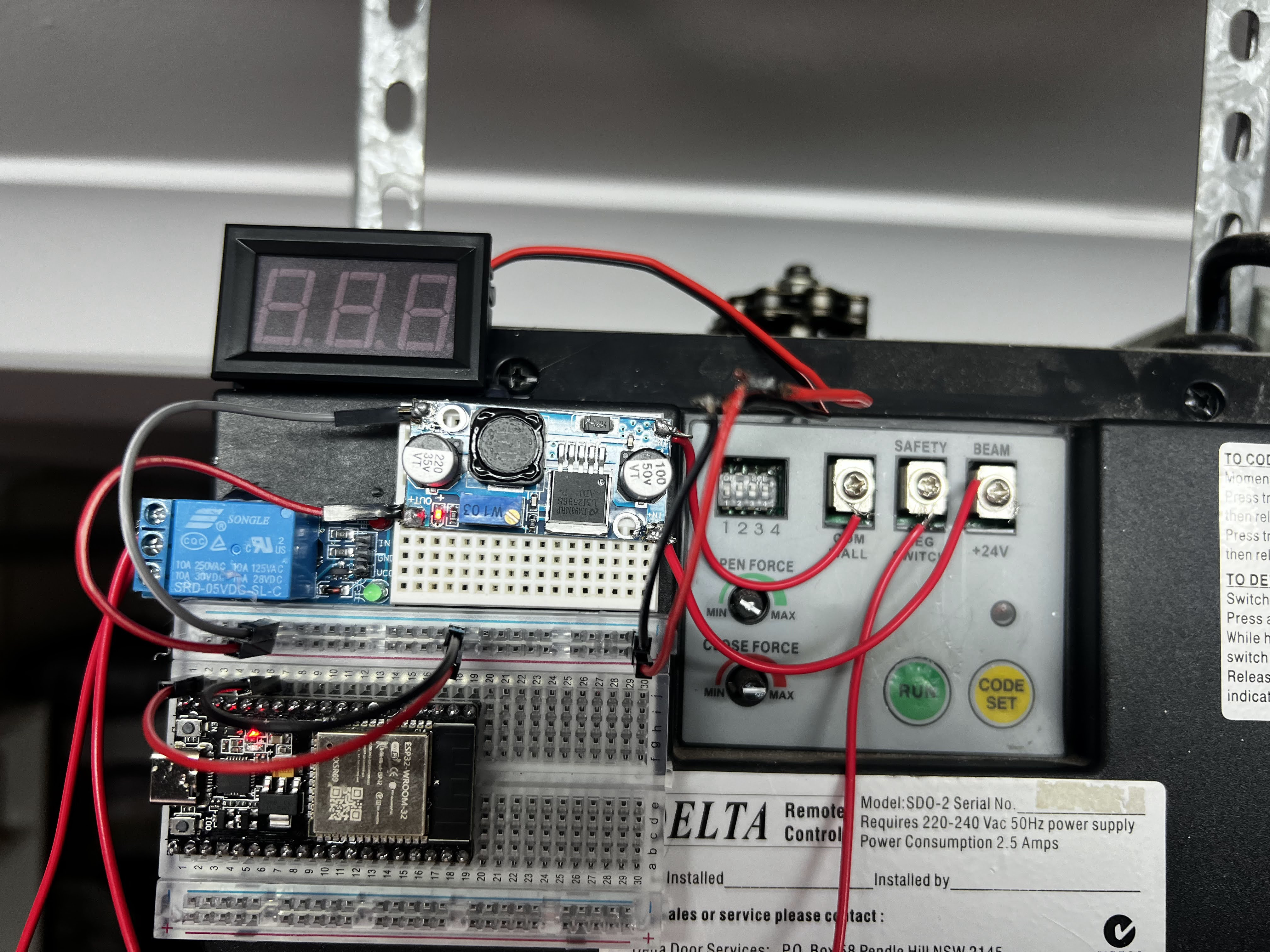
When the relay activates, the NO terminal closes to COM for about one second, triggering the door to open or close. When the relay deactivates, the terminals separate again, preventing multiple toggles.
This wiring is simple, but it’s the true magic of the entire project - the moment your ESP32 gains the ability to physically control the garage door.
A clean wire diagram can be seen here:

The Software
Now comes the fun part - teaching the ESP32 to speak HomeKit.
This section is all about the firmware:
- Connecting the ESP32 to Wi-Fi
- Creating a HomeKit Garage Door accessory
- Handling open/close requests
- Triggering the relay
- Keeping HomeKit updated with the correct door state
- Debugging via Serial
- Flashing the firmware onto your ESP32
💾 Getting the Code
If you don’t want to mess around with writing this code from scratch, that’s totally fair. You can download the source code as is, here:
https://github.com/will-lumley/GarageDoorOpener-ESP32
The repo includes:
- Full firmware source
- README with wiring diagram
- Flash instructions
If you just want your door to open in the Home app, clone the repo and flash it. If you want to learn how everything works, keep reading!
The IDE we’ll be using is Arduino IDE, which you can download from:
https://www.arduino.cc/en/software/
I recommend downloading the source code first, and then following along as I explain the important chunks.
🍏 Why Use HomeSpan?
To expose a device to Apple HomeKit, manufacturers normally need:
- Apple’s MFi chips
- Auth co-processors
- Licensing agreements
- A full security compliance test suite
HomeSpan bypasses all of that by implementing Apple’s HAP protocol directly on the ESP32.
It’s local, private, extremely fast, and works beautifully.
With HomeSpan:
- The ESP32 becomes a full HomeKit accessory
- Siri can open/close the door
- Automations work (e.g. “Open when I arrive home”)
- Everything stays in your local network (no cloud)
If you’ve ever used commercial HomeKit garage openers, this behaves identically.
🧱 Firmware Overview
Here’s what the code does in plain English:
- Boot ESP32
- Connect to Wi-Fi
- Start HomeSpan and advertise a “Garage Door Opener”
- Listen for HomeKit commands
- When HomeKit requests open:
- Update the door state to Opening
- Pulse the relay
- Update the state to Open
- When HomeKit requests close, do the same in reverse
- Keep reporting real-time status to HomeKit
The implementation is surprisingly small thanks to HomeSpan’s clean APIs.
🧩 The Garage Door Accessory Class
This class exposes the correct HomeKit characteristics:
- CurrentDoorState
- TargetDoorState
- ObstructionDetected
And handles the transition logic.
struct GarageDoorAccessory : Service::GarageDoorOpener {
  using Function = std::function<void()>;

  Characteristic::CurrentDoorState *currentState;
  Characteristic::TargetDoorState *targetState;
  SpanCharacteristic *obstruction;

  Function onOpen;
  Function onClose;

  GarageDoorAccessory() : Service::GarageDoorOpener() {
    currentState = new Characteristic::CurrentDoorState(
      Characteristic::CurrentDoorState::CLOSED
    );
    targetState = new Characteristic::TargetDoorState(
      Characteristic::TargetDoorState::CLOSED
    );
    obstruction = new Characteristic::ObstructionDetected(false);
  }

  void open() {
    targetState->setVal(Characteristic::TargetDoorState::OPEN);
    update();
  }

  void close() {
    targetState->setVal(Characteristic::TargetDoorState::CLOSED);
    update();
  }

private:
  boolean update() {
    if (targetState->getNewVal() ==
        Characteristic::TargetDoorState::OPEN) {

      currentState->setVal(Characteristic::CurrentDoorState::OPENING);
      if (onOpen) onOpen();

    } else {
      currentState->setVal(Characteristic::CurrentDoorState::CLOSING);
      if (onClose) onClose();
    }
    return true;
  }
};
This is the exact behaviour Apple expects for a garage door accessory.
🔁 Relay Control Logic
This triggers the garage opener.
void toggleRelayPin() {
  pinMode(RELAY_PIN, OUTPUT);
  digitalWrite(RELAY_PIN, HIGH);
  delay(1000);          // hold relay closed for 1 second
  digitalWrite(RELAY_PIN, LOW);
  pinMode(RELAY_PIN, INPUT);
}
One second is the sweet spot:
- Long enough for the opener to register
- Short enough to avoid double toggles
- INPUT mode prevents accidental retriggering
📡 Wi-Fi & HomeKit Setup
homeSpan.setPairingCode("11112222");
homeSpan.setWifiCredentials(ssidChar, passChar);
homeSpan.begin(Category::GarageDoorOpeners, "Garage Door");
When this runs, the ESP32 appears in the Home app just like a certified accessory.
Here’s what pairing looks like:

🧭 Door State Timing
HomeKit expects realistic transitions - not instant jumps. This loop updates the state after a delay:
void loop() {
  if (currentState->getVal() == targetState->getVal()) return;

  if (targetState->timeVal() > 5000) {
    currentState->setVal(targetState->getVal());
  }
}
You can adjust 5000 ms for faster or slower doors.
🧪 Flashing the Firmware
Okay, now it’s time to compile the code and push the binary onto the ESP32 itself.
We’ll be using the Arduino IDE to do this.
Our first step here will be to install ESP32 support for our Arduino IDE.
- Go to File > Preferences (on Windows/Linux) or Arduino IDE > Preferences (on macOS).
- Find the “Additional Boards Manager URLs” field and add
https://espressif.github.io/arduino-esp32/package_esp32_index.json - Select the “OK” button
- Go to Tools > Board > Boards Manager
- In the Boards Manager, type “ESP32” into the search bar
- Find “esp32 by Espressif Systems” in the search results
- Click the “Install” button next to it.
Once this is done, open up the garage-door-opener.ino that was in the Github repo, select the ESP32 device in the top toolbar, and press the “Upload” button.
🏁 The End Project
After everything was wired, flashed, paired, and tucked neatly back into the garage opener housing, the moment of truth finally arrived. I opened the Home app, tapped the new Garage Door accessory… and the relay clicked, the motor hummed, and the door started lifting exactly as it should.
It felt kind of surreal watching this old, very dumb piece of hardware respond instantly to Siri and HomeKit - and all powered by a $5 ESP32 and a few lines of firmware I wrote myself. No cloud APIs, no subscriptions, no vendor lock-in. Just a clean, local, reliable smart upgrade that I completely control.
In the video below, you’ll notice a little voltage meter sitting next to the ESP32. That wasn’t part of the final design - I added it temporarily while troubleshooting some weird voltage drops coming from the garage opener’s 24V supply. Under load, the voltage would momentarily dip lower than expected, and I wanted to be absolutely sure the ESP32 wasn’t browning out or rebooting mid-operation. The meter helped confirm that the buck converter was regulating cleanly and that the ESP32 was staying rock-solid throughout the relay pulses. Once everything proved stable, the meter came out and the project was fully enclosed.
What I love most about this project is how simple it actually is once you understand the pieces. A momentary switch, a relay, a microcontroller, and Apple’s HomeSpan framework - that’s all it takes to breathe new life into an aging garage opener.
Here’s the final setup in action: